Exercises on the Basic Triangle
I’ve made the OpenGL triangle before, but now I’m trying to draw 2 triangles side-by-side with their own VAO and VBO.
So it looks like you would need to make 2 separate draw calls, which is what I thought would have to happen. This is because we need to change which VAO is binded in the OpenGL state machine. I am wondering how we would do this when lots and lots of data is being drawn. Would we swap VAO’s every time? I imagine that would be kind of redundant, but I think this situation also doesn’t necessitate creating 2 separate VAOs. Maybe just 2 VBO’s, since it is possible for a VAO to refer to multiple. Since all data is the same size/type, it would also make sense.
I’m also confused why we repeat this code for each VAO/VBO combo:
    // tells OpenGl how to interpret the vertex data in the memory
    // first arg - pass data to the vertex attribute in location 0,
    // second - size of the vertex attribute (vec3)
    // third - type of data (float), fifth - distance to next vertex attribute (3 floats),
    glVertexAttribPointer(0, 3, GL_FLOAT, GL_FALSE, 3 * sizeof(float), (void*)0); // ** points to data and defines its layout
    glEnableVertexAttribArray(0); // ** enables attriubte in location 0
The only reason this would make sense would be if the VertexAttribPointer refers to something within the specific VBO that’s binded. Is VBO synonymous with buffer? Also, if the vertex attribute array wasn’t enabled in location 0, what would happen?
NOTE
A
VertexAttribPointerstores the relevant info that details how to use the VBO (buffer) data inside of the binded VAO. So yes, it’s required for the buffer object for each VAO! Also, it will not read the location 0 if disabled.
It’s also very intuitive to switch shader programs - call glUseProgram(newShaderProgramHere)
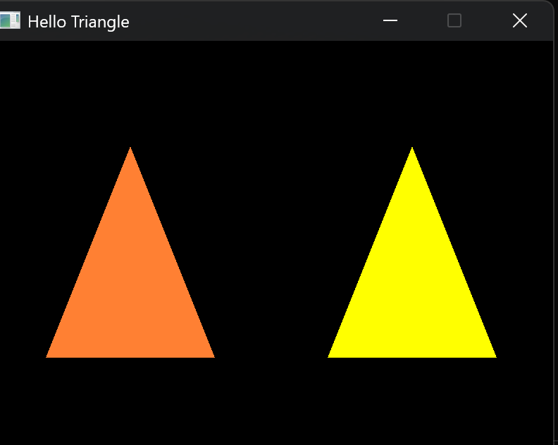
Here’s 2 triangles with different colors using that:
Shaders
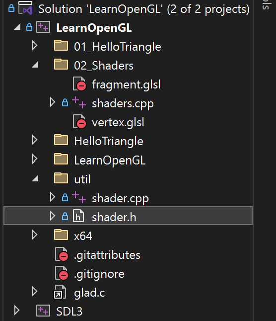
Oh my I just spent 2 hours changing my file structure and writing a Shader class (first ever C++ class by the way). Anyway, now it’s pretty and I don’t have to write a lot of verbose logic for this next section.
 I was going to sleep, but I’ve been trying for 2 hours, so back to it, and I’ll finish this chapter.
Okay, I made a triangle go green and black and back by updating a fragment shader’s uniform variable with SDL’s time-elapsed equivalent. Uniform’s actually make sense now as the u_time and iTime variables I was using so freely in GLSL.
Now to make a rainbow triangle! I know how to do this in GLSL so I’m interested how I can feed the data from OpenGL :)
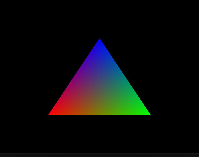
And yippee a rainbow triangle! So the 5th argument to glVertexAttribPointer actually sets the initial offset in the VAO for that location, which is cool! I also totally didn’t expect it to sort-of auto interpolate colors like that. Literally all I did was define a color for each of the vertices, and then plugged it into the shader with an input color, and somehow the 3 input colors turn into that. I guess it makes sense to a degree because how else would the triangle be filled anyway and not just 3 points on a black screen. But that color interpolation seems like a black hole… I also wonder if there is a way to set the interpolation to cubic, etc…
Oh my god. We are literally doing in this chapter what I tried doing by myself earlier. Oh my god.
Back in 8 hours.
First Challenge - display triangle upside down
light work, just reverse aPos.y while also reversing aPos.x to maintain proper winding order
Second Challenge - move triangle anywhere via uniform
I messed up.
Went extra to make the triangle move in a circle. Accidentally made the sin value 10 times higher than the cosine for the y-offset. Got it working after.
Third Challenge - send vertex pos to frag shader
I did it + some extra, keeping the circle movement. For this challenge, there’s a question asking why parts of the triangle are black.
My guess is that the bottom left of the triangle is the color part representing Z. Red and Green are shown because they correspond to X and Y when feeding the vertex position straight to the fragment shader as the color. Z is set to 0 because our vertices are flat with no Z value.
Okay, I was wrong. It’s because the position is negative there for X and Y so that also clamps to 0, in addition to Z being 0 already.
As a side note, I wonder if there’s a way to make it so vertices aren’t interpolated and other images aren’t drawn. I also was wondering how it determines which vertex gets green, etc., but it’s just because the tallest vertex is the one with the greatest Y value; therefore, it appears the greenest. The same happens for the rightmost vertex with X and Red.
Is the fragment shader called for every vertex (only 3) or called for every pixel? Every pixel would make sense. Online research confirms this via rasterization, which precedes the fragment shader in the pipeline.
Textures
Texture wrapping
Standard textures stuff. There’s the modes for texture wrapping (mirror, repeat, clamp edge (stretches outermost pixels to the edge of the object), and clamp border (cuts texture and uses a specified border color for the rest of the object). You can specify this per dim, like st.x and st.y.
Texture filtering
We got nearest, which chooses the texture pixel that centers closest to an object’s pixel (with a typically larger res). Then we have linear which just mixes the nearest texture pixels, preferring ones it’s closer to. Nearest is like an upscale low-res look while linear can often become muddled and blurry but smoother when the texture is low-res. Linear is generally more realistic. You can also specify when to use which, like if the texture is bigger, use linear, else nearest which is cool.
Mipmaps
Creating textures that are twice as small as the previous ones, and then selecting which one to use based on the distance from the camera.
OpenGL has something to do it automatically🔥
You can also interpolate between mipmaps with Linear or have it select the Nearest mipmap! But you can’t use mipmaps with texture magnification (when making textures bigger onto higher-res objects) since mipmaps are smaller versions of the texture by default and scaling up a smaller version of a texture doesn’t really make sense because it defeats the whole point.
Image Loading.
Everything takes a super long time in low-level systems! Supporting a bunch of different file types and the like is difficult, which is why we just use a C++ library instead! There’s stb_image.h for easy things, which is what is recommended by the tut.
Using texture data
Pass it the same way we pass colors and positions, putting it in a buffer object and updating the VAO. We’re using a square from the first OpenGL part with an EBO but I never actually did that, so doing it rn.
We set the EBO the same way we do a VBO, and we also still need to have both objects, as EBO just says “draw this amount of data in this order and then reuse it to draw these other things.”
Why do we include draw instructions in the buffer object creation?
Because it determines where it’s put in memory (only accessed once, read-only, etc)
We also use it in the shaders the same way as colors and positions, but the difference is that we also need access to the texture in the fragment shader and not just the texture coordinates. We set the texture using a uniform in the fragment shader, and if we bind the texture before drawing, OpenGL automatically sets that uniform.
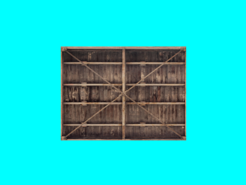
What happens when we need to draw different textures?
Looks like
glBindTextureactually puts them into a slot 0 by default. We can manually put textures in different slots to use multiple, but I’m sure it introduces some complexity for how to get those textures into the fragment shader.
Wow! This was actually the next step in LearnOpenGL again. We can just activate different texture slots and then bind textures to get them into those slots. It seems useful here to create a 2d texture creator func or Texture2D class but I’ll wait and hope the tuts get to it. We also have to set the uniform int values now for the textures, setting texture1 = 0 and texture2 = 1, corresponding to their locations in the slots.
After mixing them, we get this:
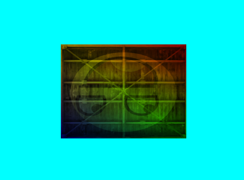
It’s upside down because images usually have 0.0 as the top of the y-axis instead of at the bottom like OpenGL. Can flip using stbi_set_flip_vertically_on_load(true).